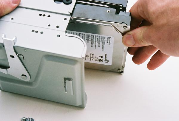
We assemble and install our two drive SATA array at this point for the simple
reason that the drive cage can't be removed once the PCI Express video adapter
is installed. The 3.5" drive cage is supported and secured by metal guides
and a locking lever. The locking lever is pushed towards the inside of the
case, and the whole cage slides out horizontally with very little resistance.
Figure 39: Removing the 3.5" drive cage
We'll be installing two 3.5" Seagate Barracuda SATA high performance hard
drives. There are two bays in the cage equipped with shock absorbing rubber
mounts, which help protect the hard drives from vibrations in the case. In
order to use the bays with the shock absorbing mounts, the drives can only
be installed in an upside-up orientation; the screw holes won't line up any
other way.
Figure 40: Installing the first Seagate Barracuda drive in the cage
The drive is secured with four special screws that were supplied with the
case hardware. Over tightening the screws would simply crush the rubber mounts,
so don't run the screws in with all your strength. One of the screws with
its unthreaded upper shaft is shown sitting on the side of the hard drive
to the left of the screwdriver.
Figure 41: Securing the hard drive
The second hard drive is installed in the cage right above the first. The
advantage of the removable drive cage is that the drives can be aligned and
secured with screws on both sides without having to access the other side
of the case. The top two bays in the cage could be used for a floppy drive
and another 3.5" drive, but we won't be installing either in this build.
Figure 42: Installing the second Seagate Barracuda hard drive
With both drives installed in the shock absorbing bays of the drive cage,
you can see that there's a small air space between them. The drives do not
touch each other. A tower case, like that used in our Chapter 6 build, has
multiple removable drive cages that allow for greater drive spacing.
Figure 43: Securing the second drive with four screws
The drive cage is reinstalled in the case infrastructure by sliding it in
on the horizontal. This means there must be an open space in the case as
deep as the length of the hard drives, which is why we had to install the
drives before the video adapter.
Figure 44: Sliding the cage into the case infrastructure
While the drive cage is supported in the vertical plane by the case
infrastructure as soon as it's slid into place, it will still slide in the
horizontal until you close the locking lever. The lever should operate with
very little resistance, if it seems to be bound, remove the cage again and
make sure it actually slid in properly on the guides.
Figure 45: Locking the drive cage into place
Next we install our SATA power connectors on the drives. This is another
step that we are taking now simply because it would be very difficult to
carry it out once the video adapter is installed. The two SATA power connectors
are fit on the smaller edge connectors of the hard drive, and they are keyed
so they can only be installed in the proper orientation.
Figure 46: Installing the SATA power connectors
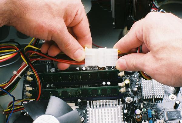
New power supplies all ship with SATA power connectors as standard option,
but at the time we built this system, power supplies required a simple adapter.
In this case, we used an SATA power adapter, two connectors located on a
4 wire cable bundle, which is then connected to a standard 1x4 connector
from the power supply.
Figure 47: Connecting the SATA power adapter to a power supply lead


No comments:
Post a Comment